In this lab you will be using the Arduino to apply power to an LED. You will not be programming the Arduino. The diagram below shows an example of how to hook up your LED. Some things you should be aware of.
- You do not have to use the same colours for your wires. The colours in the diagram are so you will know which wire the instructions are referring to but you can use any colour you like as long as you don’t get mixed up.
- You don’t have to put the devices in exactly the same holes as the diagram but you do need to be aware of how the bread board works. On the sides are two columns that are two holes wide. Each of the columns are joined together. That means if you put two wires in the same column they will be joined. If you put them side by side (different columns) they will not be joined. We use the columns as the power supply rails. the left hand column is the positive side and the right hand column is the negative or ground side. In the middle of the board are two blocks of thirty rows of five columns each. The columns are labeled “A”, “B”, “C”, etc and the rows are numbered “1”, “2”, “3”, etc. There is a central gutter down the middle of the board. In any numbered row, the holes “A” to “E” are all joined together and the holes “F” to “J” are joined. There is no connection across the gutter.
- The LED you are using has been mounted on a small circuit board and has some tiny resistors on the board that mean you can plug the LED straight into the power. That’s why it looks different.
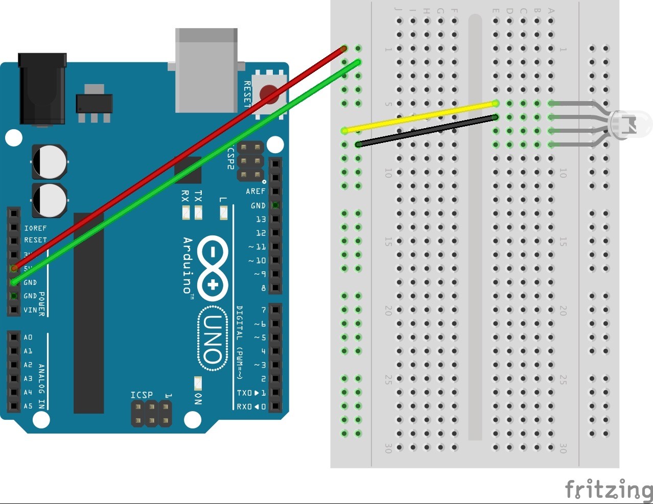
In the diagram the 5V from the Arduino is connected to the left column on the right hand side. That means that anything plugged in to that column is all connected to the 5V supply. The yellow wire connects to that column and it also connects to the positive pin (anode) of the RED LED. The black wire connects to the ground or negative side of the LED and also to the right hand column on the far left of the board. This column connects to the GND of the Arduino and completes the circuit.
Investigate:
Try connecting the yellow wire to the LED to a different pin.
Try adding more wires from the 5V supply to the other LED pins.
Use this attached document to record your progress and to describe the results of your experiments.
Now think about how you might apply what you have learned in your project.